What is a Breadboard?
Get NowA breadboard is a rectangular plastic board with hundreds of tiny holes used to build prototypes of electronic circuits. It's the playground for your electronics.
In the old days, people literally used their mom's wooden bread slicing board and hammered nails into it. Thankfully, we have the solderless plastic version today!
Why do we use them?
- [+] No Soldering: No melting metal required.
- [+] Reusability: Use components for 1000+ projects.
- [+] Speed: Fixing mistakes takes seconds.
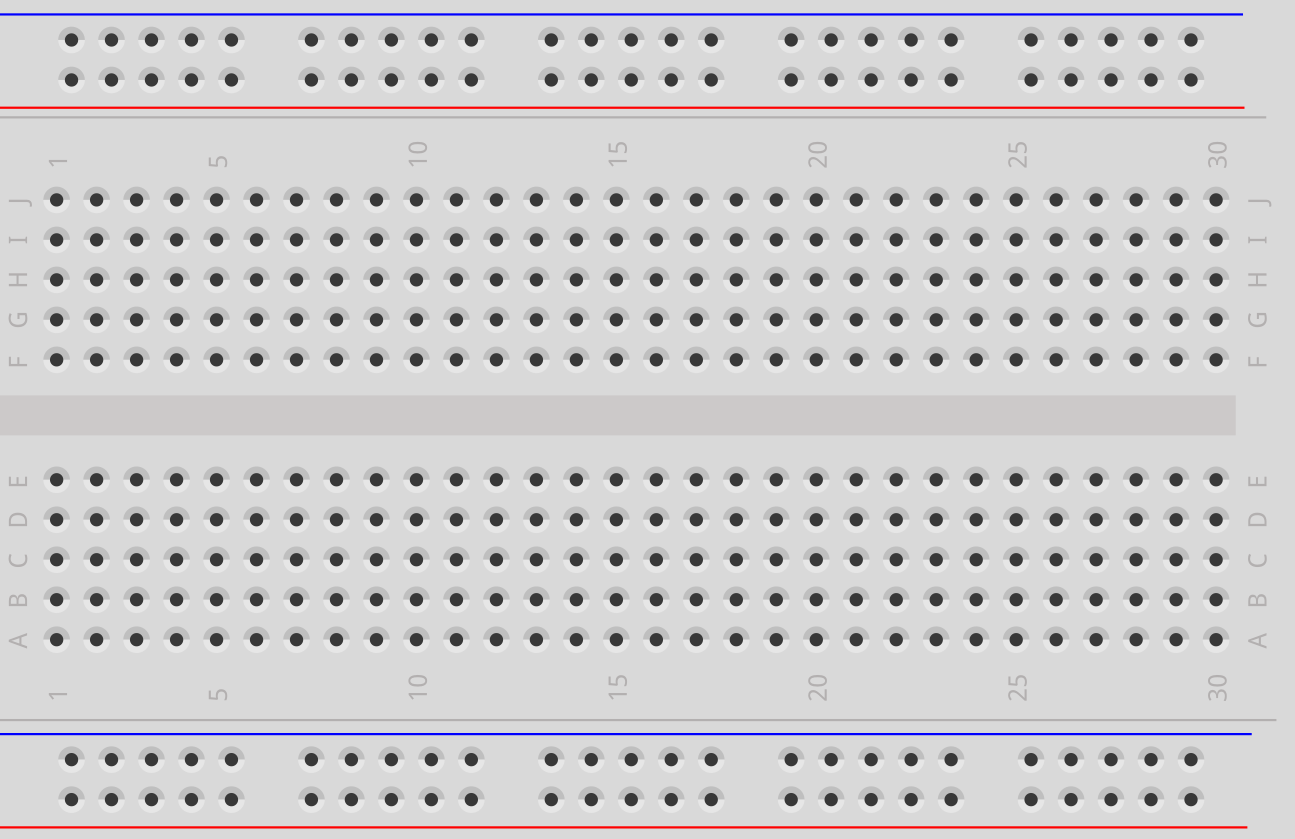
Fig 1. Standard Half-size Breadboard
The Layout: How is it Connected?
Components are hidden inside the plastic. Understanding the hidden metal clips is crucial.
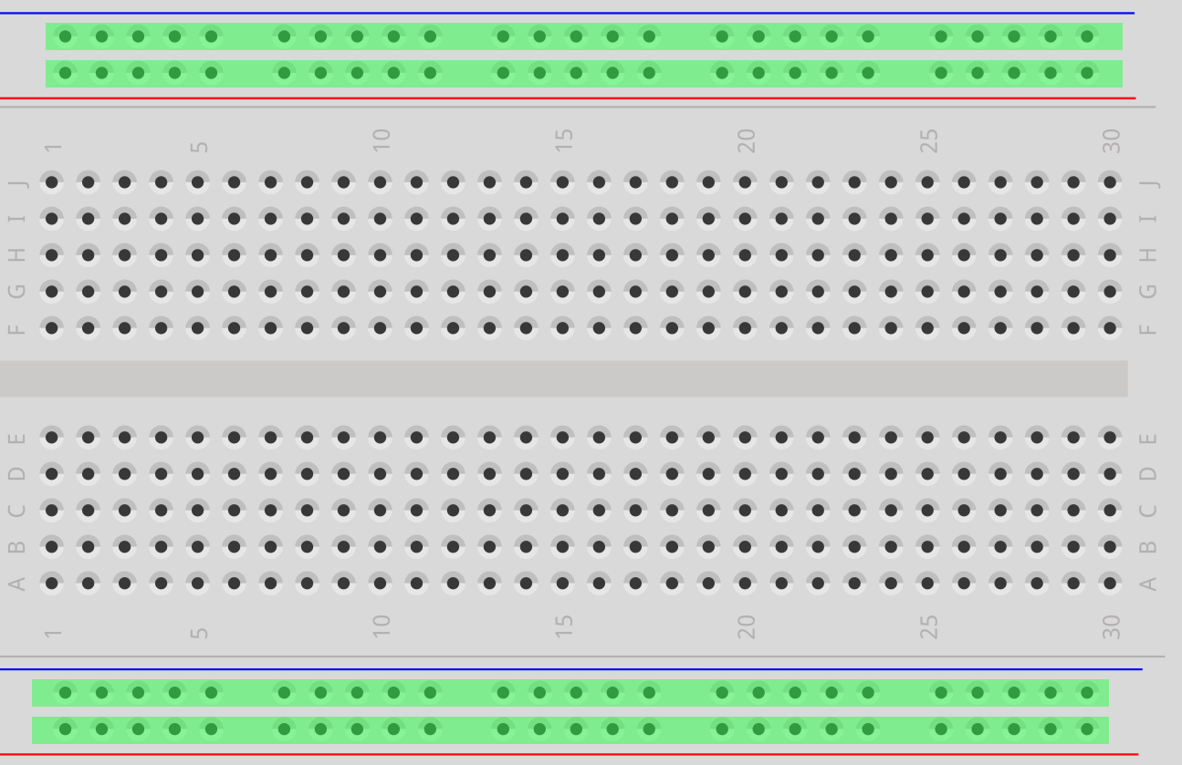
The Power Rails
The "Highways" on the top and bottom (Red/Blue lines).
- Red (+): Positive Voltage
- Blue (-): Ground / Negative
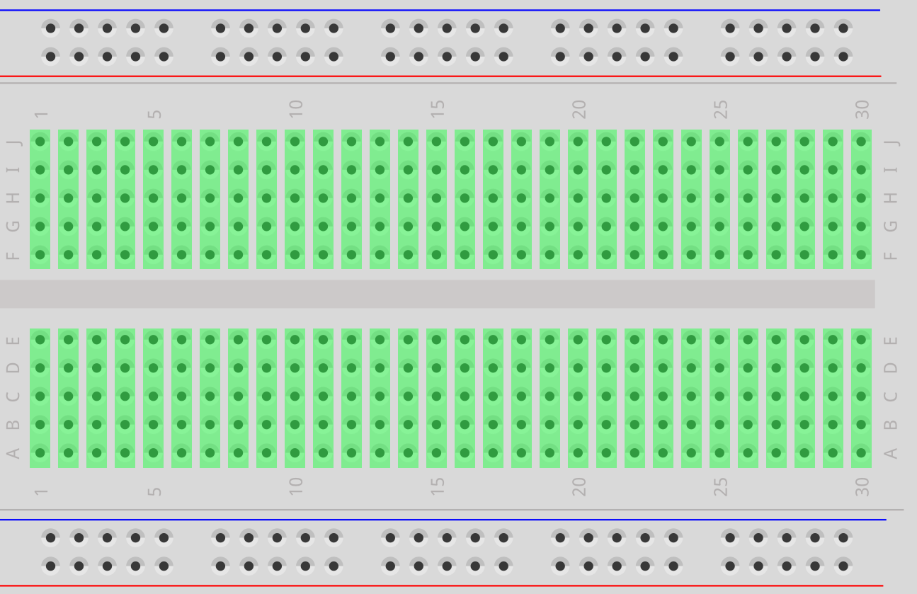
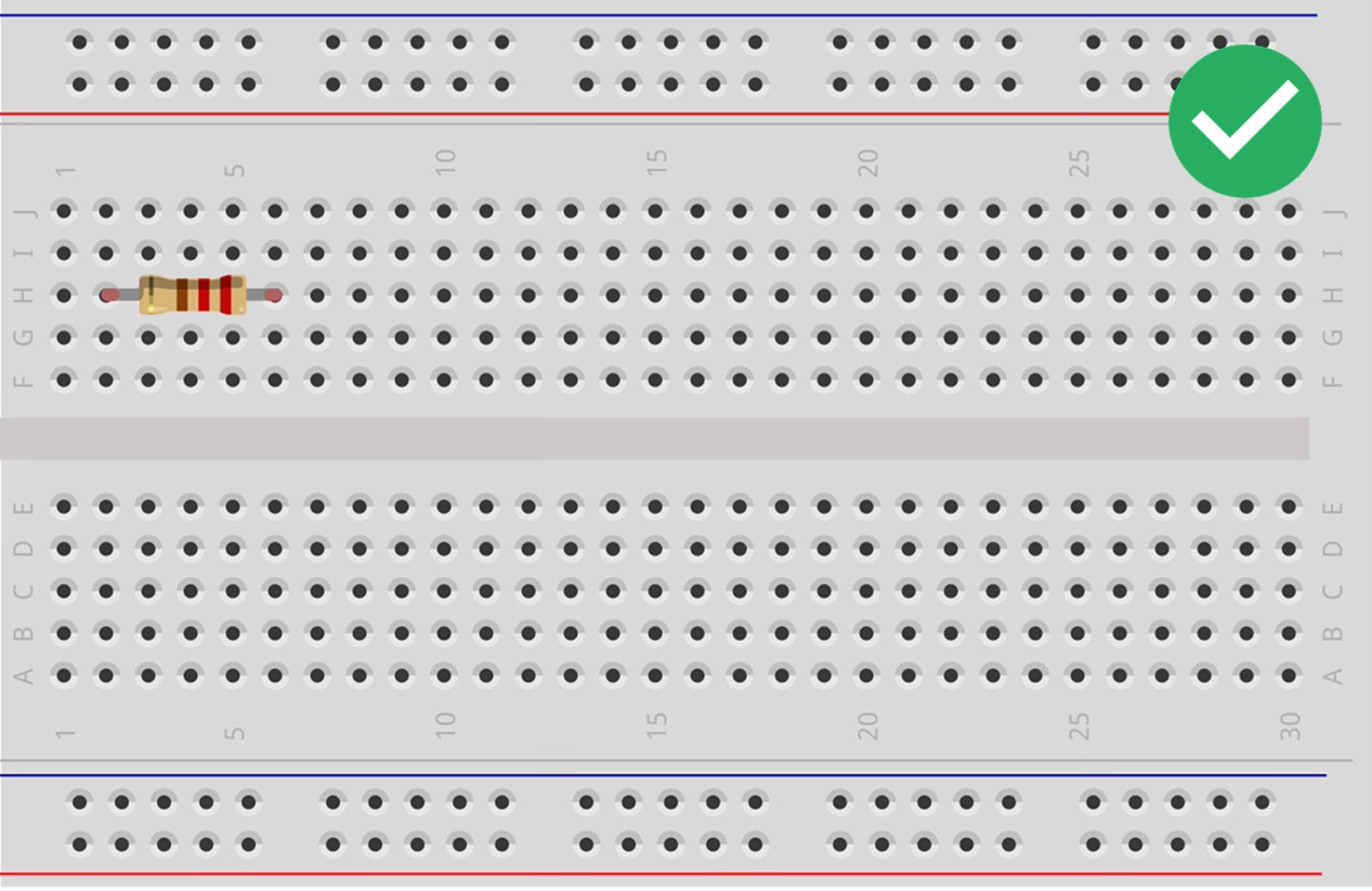
The Terminal Strips
Rows in the middle connected vertically. Groups of 5.
Important: Row 1 is NOT connected to Row 2.
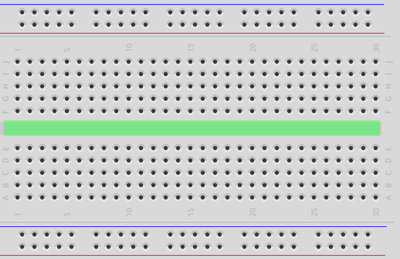
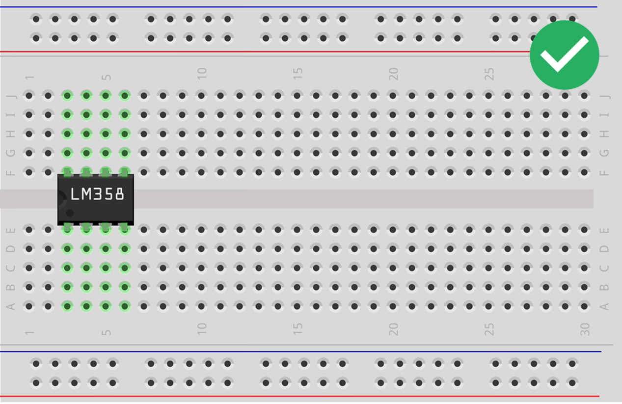
The Center Divider
Central channel isolating top (A-E) from bottom (F-J) rows.
Row 1A connects to 1E, but stops at the ravine.
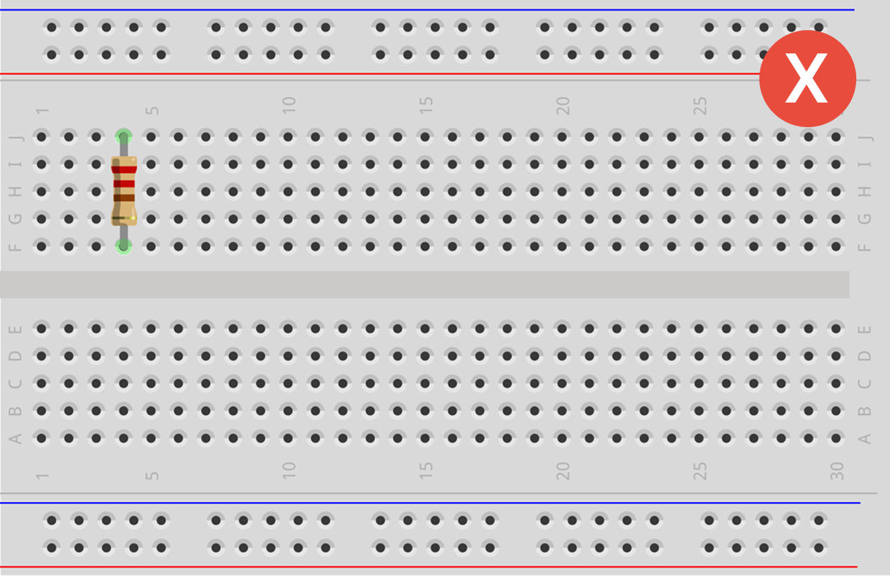
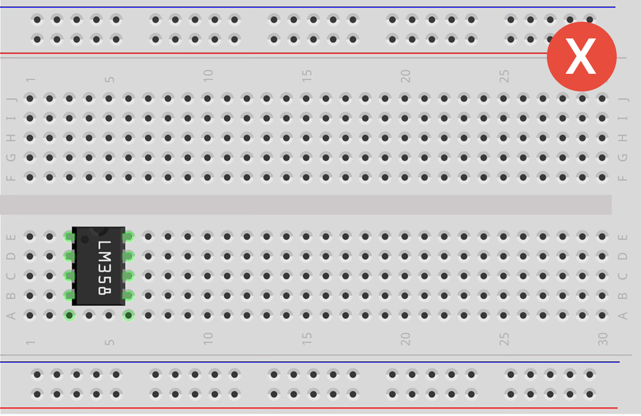
Rules for Attaching Components
Avoid the "Short Circuit".
Tips for Success
- [Push Hard] You should feel a distinct "click". Brand new boards can be stiff.
- [Color Coding] Red = Power (+), Black/Blue = Ground (-). Don't mix them up!
- [No Spaghetti] Lay wires flat against the board. Loops are hard to debug.
Jumper Cables: The Veins

Male-to-Male (M-M)
Pin on both ends. Most common. Connects holes on the board.
Male-to-Female (M-F)
Pin on one end, hole on the other. Connects sensors to board.

Female-to-Female (F-F)
Slots on both ends. Connects two sensors together.